Roman Cisar and his "Universal Component Tester Project"
In the 3rd year of vocational school, we were not only offered project-oriented lessons for the first time, but were also given the opportunity to lead an interdisciplinary project ourselves. We had the choice between a running light and a versatile component tester.
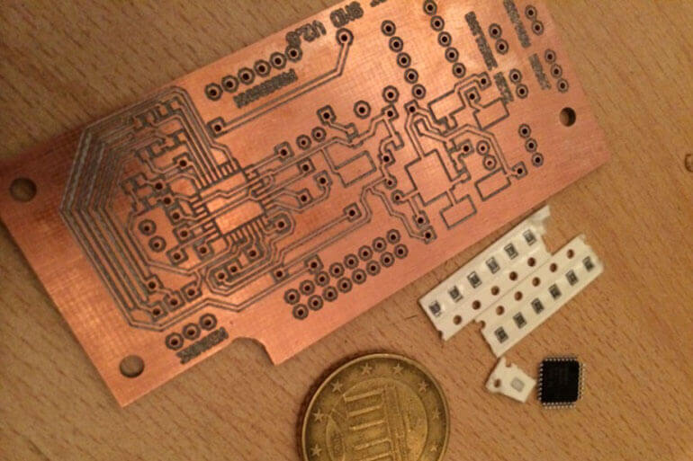
When we received the circuits, I was completely fascinated by what this component tester could test. This awakened the perfectionist in me, as I wanted to turn a great circuit into an equally great product. In the first semester, I started planning and collecting ideas, and I suspected that my project would be very time-consuming. Back at CANCOM Austria Components, I told them about the great project we had started at school. Naturally, I asked our excellent prototyping team for electronic and mechanical help. I quickly realized that my ideas were good, but not always feasible, so it was back to the drawing board. This time, however, not on my own, but with expert support from the KCO prototyping department and professional software. The idea was to replace my originally planned housing made of bent aluminum sheet with a milled aluminum block. This was of course very welcome, as I was able to acquire drawing skills using AutoCAD software, CNC programming and some mechanical knowledge. Once the housing had been manufactured, it was time to design the electronics, and as I once again didn't want to make life too easy for myself, I designed two circuit boards. One with wired components (as required by the vocational college) and another with SMD components to demonstrate my skills. Of course, this went down very well at the vocational college. Back at the vocational college after the practical work in the KCO, the second block was dedicated to producing the circuit board. The final assembly could then begin with the finished circuit board, during which I still had to make one or two small adjustments. When everything was as I had imagined, I was able to present a great end product with a good 75 pages of documentation, which naturally impressed my teachers.
The Universal Component Tester project:
The Universal Component Tester is a versatile measuring device for component testing. It has a large 16x2 LCD display with blue backlighting on which it outputs the detected components. The evaluation is carried out by means of a programmed microcontroller (ATMEGA 8), which of course carries out the entire measurement and supplies the data to be output to the display. For measurement, 2 x 3-pole adapter cables can be connected to the tester, which can be used as required and according to the type of measurement. Once in a mini-hook and a fine measuring tip version. As a rule, the measurement takes approx. 2 seconds, with larger capacitors up to one minute is possible.
Automatic detection of:
- NPN and PNP transistors
- Diodes
- Thyristors
- Triacs
- Resistors
- Capacitors